Occasionally, a designer may ask how much current can safely be run through a given connector design. While this is a simple question, the answer is very complex. The maximum safe current depends on three parameters: connector geometry, electrical resistance, and maximum allowed temperature rise. The influence of the connector geometry is straightforward. To the contrary, the electrical resistance is a dynamic, uncertain quantity that depends on a number of other interrelated factors. Similarly, many factors affect the maximum allowable temperature.
In hardware stores, it is common to see heavy-duty extension cords rated at certain current levels, such as 10 or 15 Amps. This is the maximum recommended current that can be passed through the cord without compromising safety. This level is known as the cord’s current carrying capacity, or ampacity. This leads to a common misconception that a given material has a maximum amount of electrical current it can handle without failure. This is false, since there are many different possible failure mechanisms for a given current-carrying situation. Instead of asking, "How much current can be sent through this material without failure?" One should ask "How much current can be sent through this contact before the temperature rise causes one of its performance criteria to fall below a critical value in a specified amount of time?" This is a very complicated question, and there is a good reason: the subject matter itself is quite complicated.
When an electrical current is run through a conductor, the intrinsic resistance of the material converts some of the power in the current into thermal energy. It is important to understand how connector geometry and material choice influence the temperature rise experienced by the connector as the current flows through it. Temperature rise is minimized by using larger cross-sectional areas and shorter conducting lengths. (Note that this would also increase the stress and force experienced by each contact in the connector.) Materials with greater electrical and thermal conductivity experience a smaller rise than higher resistance materials. More importantly, the temperature rise is directly proportional to the square of the current. These factors account for all of the easily controllable variables.
Other variables also come into play. The electrical resistance of the contact interface may change over time, if there is corrosion product or loss of plating through wear. Indeed, higher temperatures will increase the rate of corrosion product buildup. Additionally, stress relaxation may decrease the normal force of the contact, further increasing the contact resistance. The electrical resistivity of the material itself increases with temperature, adding to the temperature rise. In the extreme case of thermal runaway, the temperature will continue to increase to the point that the conductor will melt, permanently interrupting the circuit. In fact, this is how fuses work.
Figure 1 displays the complex interaction among the design variables, material properties, and the key performance parameters of the contact. If a variable influences another variable, this relationship is indicated by an arrow. A plus sign indicates that there is a positive relationship between the variables (i.e., as variable one increases, so does variable two). A minus sign indicates that there is a negative relationship between the variables (i.e., as variable one increases, variable two decreases). For clarity, design variables are shown in blue, material properties are in green, and any parameters that decrease connector performance are in red. Contact force and stress, shown in black, are secondary design variables influenced by the primary design variables.
When addressing temperature rise, the design goal should be to ensure that under the maximum anticipated current, there should be no unacceptable increase in contact resistance. This involves determining the approximate expected temperature rise, and then determining if the resultant temperature will lead to any negative effects, such as stress relaxation, loss of contact force, and interruption of the contact interface. The question to ask is, "How does one maximize the contact force over the life of the connector, given the anticipated temperature increase?"
To overcome the effects of elevated temperature, one must design the contacts with either larger cross sections or shorter lengths. When all current trends are toward miniaturization, it is easier to shorten than it is to thicken or widen the contact. A greater contact force is imperative, which requires higher stress in the contact. This requires a material with both higher strength and better resistance to stress relaxation. Additionally, high electrical and thermal conductivity in the contact spring material minimizes the negative thermal effects. Luckily, high Performance Materials like copper beryllium provide all of these benefits.
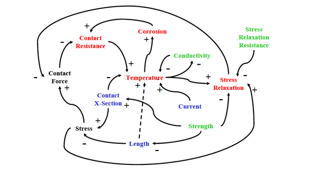
Figure 1. Dynamic interaction among design variables, material properties, and performance parameters that influence temperature rise.
Thanks for joining me for another edition of In Our Element. For ongoing industry updates, connect with me on LinkedIn.