Current North American ergonomic regulations call for the insertion force in automotive wire harness terminal connections to be no more than 75 N. Rumors have been circulating that the next round of regulations will reduce that amount to no more than 50 N. Automotive connector companies find themselves asking the question, “How low can we go?”
A schematic of the contacts in a typical interconnection system is shown in Figure 1. A blade or pin in the male half of the connector will make contact with spring beams inside the female half of the connector. As the pin is inserted, it will slide across and deflect the spring beams. This generates the normal force necessary for good electrical contact. Once the beams are fully deflected and are touching only the flat contact area of the pin, the normal force will be perpendicular to the insertion direction. The insertion force then will simply be equal to the normal force multiplied by the coefficient of sliding friction and the number of contact points. However, before this steady state condition is reached, the insertion force shows very complex behavior.
For this type of connection system, the peak insertion force always will be greater than the steady state value and is usually greater than the normal force. (For the purposes of this discussion, we will assume that the male and female halves of the connector are perfectly horizontal, so that the insertion direction is horizontal as well). As the male pin is inserted, it will first make contact somewhere along the spring beam of the female end. The location of this point is determined by the thickness of the pin and the angle between the pin and the spring beam, denoted by α. As the pin proceeds further, it deflects the spring contacts, which generates the normal force. Since this force acts in a direction perpendicular to both surfaces at the point of contact, it will have both a horizontal and a vertical component. During insertion, the horizontal component of the normal force will oppose the entry of the pin. Conversely, during the extraction process, the horizontal component of the contact force will aid extraction. Since the friction force is perpendicular to the normal force, it also will have a horizontal and a vertical component as well. The horizontal component of the frictional force will also act to oppose the insertion. Therefore, the insertion force has two components - one from friction and one from the contact reaction force. Figure 1 below shows the equation for calculating insertion force. For the derivation of this equation, please see the first two references at the end of this article.
The equation shown in Figure 1 is not as simple as it may seem at first. The contact angle and the normal force change as the contact is inserted. (The coefficient of friction may vary as well.) The contact angle will be maximum at the initial contact, decreasing to zero degrees at the steady state condition. The normal force will start at zero, and will usually increase as the pin is inserted. The combined effect is to generate a peak insertion force much greater than the steady state condition, as shown in the red line in Figure 2. Conversely, the extraction force will never exceed the steady state force, since the normal force will help to push the pin out.
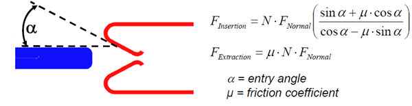
Figure 1. Schematic of connector insertion/extraction forces.
Most connectors in an automotive wire harness or on the backplane of a computer rack will have many individual contacts mating simultaneously. Even with very small normal forces, the peak insertion force can easily exceed the recommended guidelines. The only practical means of reducing insertion force are to either decrease the coefficient of friction or to decrease the initial normal force. The coefficient of friction can be decreased through the use of lubricants or more lubricious surface coatings, where possible. A decrease in normal force will increase the contact resistance, increase the chances of vibration and fretting damage, increase the potential for contact intermittency, increase the chances of accidental unmating and generally make the connection much less reliable. Therefore, a way must be found to reduce the insertion force in each contact without compromising the required normal force.
To further complicate the problem, the normal force does not remain constant over the life of the contact. It will decrease over time due to stress relaxation or permanent set from mishandling. Therefore, the normal force at the beginning of life of the connector must be increased in order to guarantee that the required force will exist at the end of life of the connector. This is where the use of the correct base metal in the spring comes in to play. A high performance base metal like copper beryllium will have the necessary combination of yield strength to avoid permanent set, conductivity to minimize temperature rise, stiffness to generate normal force and resist vibration, and stress relaxation resistance to retain normal force. This means that the designer can get away with an initial normal force very close to the required end of life value. If lower performance base metals are used, the designer may save some money on base metal costs. However, the initial normal force will have to be increased in order to maintain the necessary force at end of life. This increased normal force will generate a larger peak insertion force than one would find in the contacts designed with higher performance metals like copper beryllium. Lower priced, lower performance base metals may save some fabrication costs, but the penalty will be paid in increased insertion force and/or decreased reliability.
Therefore, high performance base metals like copper beryllium, along with lubricious platings, will allow the designer to minimize insertion force to meet ergonomic requirements without compromising the performance or reliability of the design.
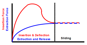
Figure 2: Relationship between insertion and extraction forces.
Thanks for joining me for another edition of In Our Element. For ongoing industry updates, connect with me on LinkedIn.