As the “Internet of Things” drives collaboration across traditionally distinct technologies, materials companies must balance maintaining traditional products with advancing next-generation ones. Recent Coating Materials News articles have focused on the complex nature of factors that influence e-beam deposition stability and consistency. Also, on materials that require increasingly sophisticated techniques to assure performance such as granule sizes, melted preforms and metals for contacts or mirrors. Before we begin digging deeper into sputtering processes, this article will address the often overlooked and practical issues pertaining to backing plates. This is an area that continues to vex engineers if only due to being legacy practices or stock.
In its simplest form, a backing plate (bp) is used to mechanically mount a target to the tool. In addition, the plate enhances the mechanical strength and facilitates cooling of the target and target assembly. Even when not directly in contact with cooling water, the bp lowers target risks due to process-induced expansion/contraction or cooling water pressure distortion. Following is a list of typical methods to affix the target to the backing plate:
-Metallic Bond
-Polymer Bond
-Diffusion Bond
-Clamp
A metallic bond maximizes the thermal and electrical conductivity between the target, plate and cooling water/diaphragm. An engineered polymer bond is used for fragile targets or when Indium, Tin or alloy intercalation and evaporation risk in the growing film is to be avoided. Both polymer bonding and diffusion bonding complicate or eliminate the ability to reuse backing plates which can add significant cost. However, diffusion bonding can hold up under the most extreme sputter powers and is common with high rate processes.
In most cases, an Indium bond layer is favored due to its reusability and excellent thermal and electrical properties. The low melting point, oxidation potential and high shear strength of Indium enables the fusing of even high CTE mismatched materials - for example Silicon and Niobium. With shear strength over three times that of its tensile strength, high CTE Indium metal (29 PPM –C CTE) can accommodate reasonable process cycles. Table 1 displays some generally recognized Linear Coefficient of Thermal Expansion values in 10-6 C-1 (PPM C-1@20C) of common backing plates and target materials.
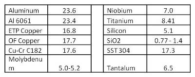 Table 1: Common Metals with CTE
When viewing the Table, it may be confusing that Copper backing plates are common with Silicon, Tantalum and Niobium. However, there are several standard Wrought Copper types in use as backing plates. These Oxygen Free (OF) or Precipitate Hardened (alloy) products are imparted mechanical energy at a range of temperatures then annealed. For use as backing plates, C10100 OFE (oxygen free - electronic grade) and C10200 OF Copper are joined by C11000 ETP (electrolytic tough pitch) grade plate. Early ETP had a host of problems and their attractive cost and availability often resulted in different types to be in stock at different times. Similarly, general industry paranoia about oxygen – even in reactive processes – filled stock rooms with more expensive and more ductile OFE plates. In all cases with copper, it is critical to have a detailed plate use tracking system as well as detailed bond/re-bond flatness protocols with the pure Copper plates.
Of special interest to Process Engineers is that standard C10100 copper has yield strength of 11 ksi (kilo –pound [force]/inch2) whereas work-hardened C10100 improves yield strength to 30-45 ksi. In processes where high conductivity or galvanic series concerns are critical, the CuCr C18200 is used and has a much better yield strength at 60 ksi. In very energetic processes, however, the CTE mismatch and thermal profile is just too extreme and target failures (debonding or cracking) are too high. In those cases, Molybdenum is increasingly used as the preferred backing plate with minimum yield strength of 90+ ksi past temperatures over 900C.
For illustration, in Figure 1 we see a generic comparison between a ductile material (Cu, Ti, Al bp) and a brittle material (Mo bp or Si target).
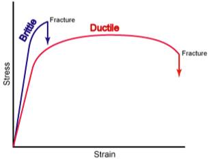 Figure 1: Generic Stress-Strain Curves
As stress (X axis) increases, the strain (Y axis) builds – promoting atomic displacement or mounting stress in the material. The more ductile materials (Copper and Titanium) will displace far sooner than the increasingly brittle rolled Tantalum, hot-isostatic press Molybdenum, and single-crystal Silicon materials. The slope of the stress/strain curves above and below correspond to the % elongation before the material yields (begins to fail). As expected, Silicon and Molybdenum (Sy (yield) and Su (ultimate) in Figure 2 would deform very little before failing.
Figure 2: Stress vs Strain: Ductile vs Brittle
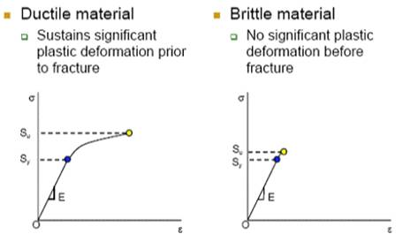
Figure 3: Comparing Yield Strengths & Basic Stress-Strain of 3 Main BP Copper Varieties to Molybdenum
Take a closer look at a ductile material Stress-Strain curve as represented in Figure 3 (for all intensive purposes C182000)
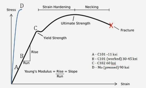
The first thing to note is the slope of the line (Rise/Run) is also the Young’s Modulus and is denoted in Figure 2 as “E.” Before the yield point (A, B, C & D) in the elastic region of the curve, a material will deform under load and then return to its original dimensions/shape when force is removed. After yielding, and until achieving its Ultimate Strength, the copper backing plates will accommodate the force and plastically deform to varying degrees until failure. Since most tool’s cooling systems initially operate well below the bursting pressure, the main issue is bowing.
With most materials, the bulge will deform soft materials (like Zinc) delaminate more stiff materials (like Niobium) and eventually crack fragile targets (like Silicon). This mechanism is a strong function of temperature, becoming more likely with reduced water flow, compromised bond and high power or density sputtering. While the more sophisticated Copper products do offer some protection from bulge – even the best backing plates can get soft over time. On the other hand, the pressed-Molybdenum plate is more resistant to deformation and has a much higher yield strength. In order to investigate the process risk of lower thermal conductivity, perhaps it would offer more insight to look into how well it conducts.
When using water-cooled backing plates for a given backing plate geometry and water pressure, the bow in the backing plate is inversely related to Young's modulus (E) of the backing plate material. Thus, a backing plate material with a higher Young's Modulus will result in lower stresses in the target. Figure 4 provides Young's Modulus for several common backing plate materials.
Figure 4: Young’s Modulus/Modulus of Elasticity of Typical BP Materials At first glance, the CTE of Molybdenum would seem to make it a more natural choice for a low CTE material like Silicon, Tantalum and Niobium. The different processing route of consolidation versus classic forge/roll should suggest that aging/annealing phenomena should be minimized. Table 2 shows that its thermal conductivity is still greater than that of Indium but still less than half of even the precipitation-hardened C182000.
Table 2: Thermal Conductivity of BP Materials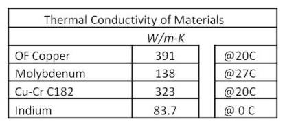 In the Interconnect/Semiconductor world, it is often important to discuss a materials’ conductivity compared to a known high conductor. This method was established as the IACS (International Annealed Copper Standard) for pure annealed copper. Having an IACS of 100% at 20 C is defined as having a conductivity of 5.8001 107 Siemens/meter. C101, 102 and 110 have IACS of 101%, 100% and 101% respectively. Molybdenum does fall short at 35% IACS but to put it into perspective, Tantalum itself is 13% IACS and Tin 15% IACS.
Several important factors outside of cost and experience can influence the appropriate choice of backing plate for a specific target and process. Beyond CTE and conductivity, engineers often need to consider the impact of sputter rate and water pressure on the target and bond.
Since the assembly spans a hot target surface via a gradient to the backside of a cold backing plate, the forces acting on the target and plate must be rationalized. In all pure Cu cases, careful water pressure, sputter power and number of uses are combined with careful observation to stave off debonding (due to bowing) or cracking (due to heat load and cracking) of targets. Alternative materials for bonding and backing plates carry their own risks. However, increasing interest in Molybdenum backing plates versus other high CTE materials may indicate a determination to overcome issues such as cracking targets or the higher heat load of reactive processes.