
The adoption of atomic layer deposition (ALD) has been strongly driven by the advanced microelectronics industry, where the trend of scale-down to smaller feature sizes necessitates the deposition of conformal films in trenches with precise control of thickness and composition.
ALD has, for example, been demonstrated its capabilities by depositing Al2O3 in mass production of DRAMs years ago. The demand of ALD has further increased with transition to high-k dielectrics, as it can be applied in DRAM capacitor and advanced CMOS transistor gate stacks of microelectronics devices. For instance, high-k metal oxide (ZrO2/HfO2) must be deposited uniformly without pinhole on Si wafer to achieve higher drive currents, enable faster high-speed ICs, and prevent leakage current in transistors.
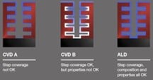
Step coverage comparison between CVD and ALD (source from ASM).
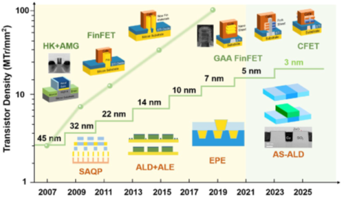
Evolution of transistor density and gate length in ICs (integrated circuits)2
In addition to continued miniaturization of devices and associated uniform deposition of thin films, the more radical concept introduction of transistor architecture from FinFET (Fin field effect transistor), Gate-All-Around, to CFET (two stack of GAA) has increased demand of ALD process to fabricate the complicated 3D stack structures(1-2).
Unlike other deposition techniques (i.e., physical and chemical vapor deposition), the ALD process is carried out by exposing the substrate to reactants consecutively. In the first step, precursor A(reactant) is introduced into the reaction chamber. It reacts with the surface functional groups of the substrate (i.e., hydroxyl and oxygen groups). Then, the system is purged or evacuated with inert gas. The precursor B(reactant) is then introduced into the chamber again and reacts with the surface. Inert gas purging and evacuating of the system follow to remove unreacted/excess precursors and byproducts. The cycle continues until the desired film thickness is achieved3.

Schematic of ALD general process3
The ALD process is typically carried out in a temperature window between 150°C and 350°C. Operating outside of this window can result in an incomplete reaction (reversible multi-layer adsorption/condensation at lower temperatures, decomposition/loss of surface species at higher temperatures).
ALD processes are classified into two groups, depending on operational conditions and precursor characteristics (i.e., thermal vs. plasma). Plasma-enhanced ALD has several advantages vs. thermal – including higher-quality thin film at lower temperatures – but its chamber configuration is complicated and thus more expensive than thermal ALD. Thermal ALD is the preferred option for conformal coating in high aspect ratios and complex structures, but it typically requires higher temperatures3.
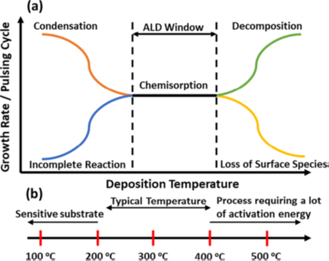
Schematic of (a) ALD growth rate as a function of deposition temperature, and (b) temperature range of precursors3
As ALD relies upon site-specific surface chemisorption, it can be scaled down into an area-specific process known as “area-selective ALD”. ALD growth cannot occur without reactive sites; thus, area-selective ALD is used in semiconductor nanopatterning. This selective deposition can significantly reduce the number of process steps required for lithography and etching4.

From left to right: A surface with chemically dissimilar areas in which ALD growth might occur (growth area) or might not readily occur (non-growth area), a surface where a blocking agent or inhibitor is selectively adsorbed on the non-growth area, and a surface after completion where material is grown only on the targeted area (blue)4.
ALD can produce a wide range of materials, as illustrated in the periodic table below. The most common are oxides, nitrides, sulfides, and pure elements. Still, it is not yet possible to grow every material by ALD. The process is mainly limited by effective reaction pathways and the availability of reactants (precursors).
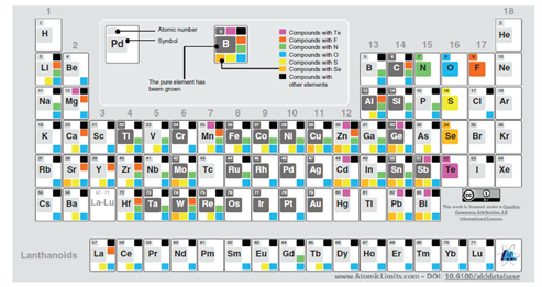
Periodic table for types of ALD materials, from atomiclimits.com, information from Miikkulainen et al. ALD material growth is shown in various colors: dark gray for pure element (i.e., Mo), yellow for sulfides, light orange for selenides, violet for tellurides, orange for halides, green for nitrides, blue for oxides, and black for compounds with other elements6.
Metal-based precursors are mainly categorized into two groups: inorganic and metal-organic (see table below). Typical non-metal reactants are hydrides and elements (i.e., H2, O2, O3) along with alcohol and others. Metal-organic materials can be further classified into organometallics if metal and carbon exhibit direct bonding. Metal halides are typical inorganic precursors and have been widely used for deposition of various thin film products. Common examples of metal-organics are metal alkoxides, amides, imides, amidinates, phosphines, carbonyl and cyclopentadienyls.
ALD precursors must display certain characteristics to create desirable reaction paths:
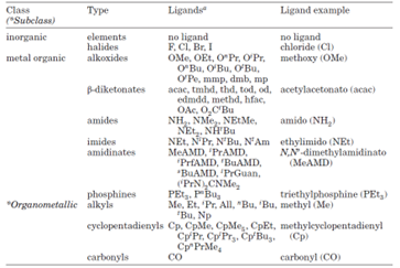
Types of precursors used on ALD processes4.
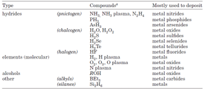
Types of non-metal reactants used in ALD processes4.
As semiconductor integration has improved and critical interconnect dimensions with existing materials (i.e., copper and tungsten) have reached their limits, research on molybdenum deposition through ALD processes has become increasingly important.
The obstacles presented by copper and tungsten are evident. Copper interconnect lines show a significant increase in resistivity as they scale down, requiring a barrier liner resulting from electromigration. Similarly, tungsten has higher resistivity compared with copper. Limited precursor availability means a relatively thick barrier is required since fluorine in the precursor damages the dielectric layer.
Molybdenum appears to be the most promising replacement material. It has a low coefficient of thermal expansion, high electrical conductivity and melting point, and a relatively short mean free path, allowing it to scale down to dimensions that do not greatly increase electrical resistivity. Moreover, because of molybdenum’s high thermal stability and expected resistance, electromigration and intrinsic diffusivity into dielectric material are limited. Thus, a barrier liner such as titanium nitride, tantalum nitride or tungsten nitrides is not required7.
Several fluorine-free inorganic molybdenum precursors are available, such as MoO2Cl2 and MoCl5 (visit www.atomiclimits.com/alddatabase for more information). Solid MoO2Cl2 and MoCl5 precursors seem to be the most attractive candidates for various applications and are being used more frequently since they are non-toxic, relatively more stable, and easier to use/handle.
These solid precursors also exhibit thermal stability, though more sophisticated process control and a delivery system are required to keep vapor pressure constant and supplied to the chamber. As an example, molybdenum thin film can be deposited on a line trench (aspect ratio: 40:1) by a thermal ALD process and exhibit good step coverage, which is critical to producing controlled miniature semiconductor patterns7.
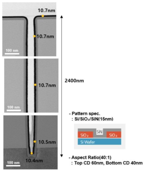
Step coverage for a 40:1 pattern of MoN (40 cycles)/Mo (140 cycles)
thin films at a process temperature of 650⁰C7.
ALD can produce thin films of a wide variety of materials, offering high conformality, thickness control, and malleable film composition. It also displays temperature flexibility, wide process windows, scalability and repeatability, making it a powerful tool for many industrial and research applications. Microelectronic device manufacturers, in particular, would do well to better understand ALD and how it can facilitate enhanced features in their products.