
Determining a material’s fatigue behavior is a crucial part of understanding if that material is a good fit for the intended use. To determine the fatigue strength, various tests must be run. The result of running fatigue tests is a list of the applied peak stress level in each sample, as well as the number of cycles that it took for each sample to fail. These data points are plotted on a chart, with the number of cycles to failure (N) on the horizontal axis, and the applied stress (S) on the vertical axis. This article will talk about how to read and use the data in the S-N diagrams.
Most S-N curves are run in the high cycle fatigue regime (more than 10,000 cycles.) At that point, the stresses are well below the yield strength of the material, so there is no plastic deformation anywhere other than the tip of the fatigue crack. Fatigue tests are typically stopped after 108 (100 million) cycles, and the result is designated as a runout. Runouts (samples that did not fail in the elapsed time of the test) are conventionally designated by an arrow pointing to the right, located at the applied stress level and the number of cycles after which the test was stopped.
Figure 1 below displays a schematic of typical curves (not including runouts).
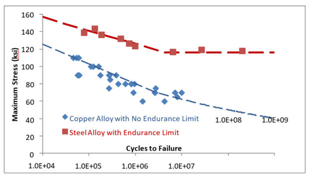
Figure 1. S-N Diagram of a Copper and a Steel Alloy
The endurance limit is a stress level below which the failure rate will not increase, no matter how many cycles the material sees. Most nonferrous alloys (based on copper, aluminum, titanium, etc.) have no such limit.
For Figure 1 above, note that there may be a large amount of variation in the data. A best fit trend line can be plotted through the center of the scattered points. This trend line does not have much use other than to provide an estimate of when about half of the tested parts would be expected to fail. Thus, the question that should be asked is this: "At what stress level would all of my parts, or at least an acceptably low amount of them, be expected to fail?" We can look at the S-N diagram to find that information.
In Figure 1, the two metals show different behavior. For the steel alloy, there comes a point where the trend line becomes horizontal. The stress level at which this occurs is called the endurance limit. A case could be made that this would be the limiting stress level for any design using this steel. However, note that the line is still around the 50% failure point, as there will be an equal number of failures above and below the endurance limit. Therefore, there should be a safety factor added into the design stress value large enough to account for this scatter. This reduced value would be the stress level below which the material would not be expected to fail, no matter how many times it is cycled, unless acted on by some external factor like corrosion.
The copper alloy shown has no endurance limit but instead has a curved trend line of continuously decreasing slope. Therefore, to define a safe stress level, one needs to know how many cycles the part would be expected to survive in service. From this, one can use the S-N data to identify the range of stresses that would result in that given number of cycles. This value would be the fatigue strength at the given number of cycles. For materials that do not have an endurance limit, this would normally be specified as the 106 (1 million), 107 (10 million), or 108 (100 million) cycle fatigue strength. This point is especially important when comparing fatigue strengths between different materials.
There are two ways to use an S-N (also called a Wöhler) diagram. The first would be to compare the peak stress level in a cycled design to determine the expected number of cycles to failure. This would usually be given as a range. In Figure 2 below, a design using this material with a peak cyclical stress of 80 ksi would be expected to last approximately 105 to 106 cycles.
The second method would be to determine the minimum required number of cycles for your design and find the minimum stress that results in a failure in that time frame. This minimum stress level would then be the limiting stress in your design instead of the endurance limit. Figure 2 shows a design expected to last 500,000 cycles should have no more than about 67 ksi peak cyclical stress. It would also be prudent to add a safety factor onto this limiting stress level, since there are many effects that may reduce the expected lifetime, such as temperature, corrosion, surface finish, stress concentration, etc.
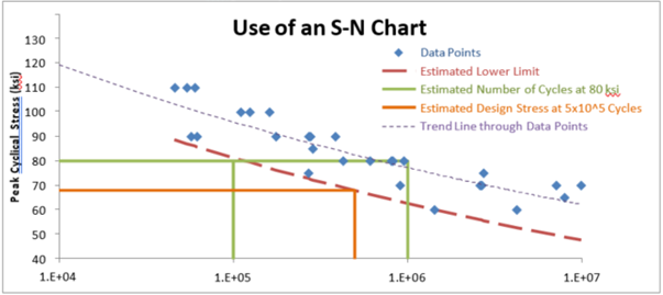
Figure 2. The Two Simple Uses of an S-N Diagram
The green lines illustrate the expected number of cycles for a peak stress of 80 ksi, and the orange lines illustrate the maximum stress allowable for a design required to last for half a million cycles. The lower limit (red dashed line) could be manually estimated or (more appropriately) derived statistically.
Using S-N diagrams can be an important factor in making sure the material you choose for your application will last under its anticipated conditions. Knowing not only the fatigue behavior but also the fatigue strength ahead of time can improve performance, longevity and safety of a product.
Learn more about materials like our BrushForm® 158 (BF 158) copper-nickel-tin strip alloys that offer increased fatigue life.
Thanks for joining us for another edition of In Our Element. For ongoing industry updates, connect with us on LinkedIn.