Before we jump into the brazing process for copper beryllium, let’s discuss what brazing is and the benefits of this metal joining method. Brazing is commonly used to join metals where high strength and resistance to high temperatures are required. Brazing copper beryllium is relatively simple and inexpensive. Most importantly, the strengthening mechanism inherent to copper beryllium makes it possible to braze without permanently weakening the alloy. Alloys such as phosphor bronzes or nickel silvers, which are strengthened only by cold work, will be permanently softened by brazing.
Brazing is defined as the joining process in which the filler or braze metal, which melts above 800°F 425°C) but below the melting point of the base metal, is drawn into the gap by capillary action. Brazing is intermediate in temperature between soldering and welding. For copper beryllium alloys, the typical brazing temperatures will be above the age hardening temperature and approximately equal to the solution annealing temperature.
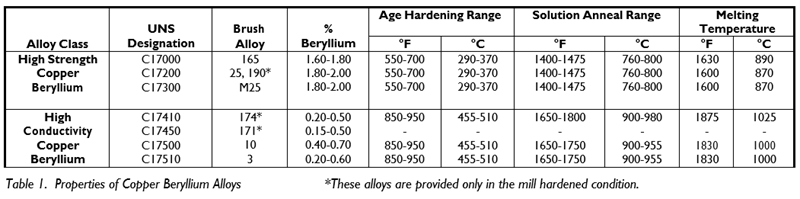
Depending upon the application requirements, copper beryllium alloys are available in two alloy classes: High Strength (C17000, C17200, C17300), and High Conductivity (C17410, C17460, C17500, C17510). Both alloy classes are strengthened by thermal treatments. (See Table 1).
First, the alloy must be solution annealed so that the beryllium is dissolved into a solid solution and is available to take part in the subsequent age hardening step. Solution annealing is always followed by rapid cooling to room temperature. Water quenching is used most often, although some thin section parts can be quenched by forced air. After quenching, parts are now in the annealed or A temper. In this condition, the parts are soft, easily formed, and have relatively low electrical conductivity. If the alloy is cold worked after quenching, the temper is designated a cold worked temper such as H. The solution anneal and quench steps are usually performed by the alloy manufacturer.
The second step is the age hardening (often called heat treating or aging) process, where hard, sub-microscopic, beryllium-rich particles are formed in the metal matrix at a temperature below the solution annealing temperature. The amount and distribution of the hard phase is dependent on the aging time and temperature, and accounts for the alloy's high strength. When an annealed or cold worked metal is age hardened, its strength and electrical conductivity increase, ductility or formability decreases, and the temper designation is followed by the letter T, such as AT or HT.
During brazing, if parts are exposed to temperatures above the age hardening temperature but below the annealing temperature, they will overage and the strength will decrease. Depending on the exposure time and temperature, the strength loss of overaged parts may be significant up to 50%.
Higher brazing temperatures, in the solution annealing range, will soften or anneal the parts. If the parts are quickly cooled from this temperature, they will respond to age hardening. When rapid cooling is not possible, parts may be reannealed and aged after brazing. In this case, care must be taken so that the solution annealing temperature does not exceed the melting point of the braze metal.
Surface cleanliness is essential to obtaining a sound braze joint. The mating surfaces must be free of dirt, oils, grease, tarnish, and oxide. A flux provides protection during brazing but is not a substitute for adequate surface preparation. Solvent or vapor degreasing is effective on organic contaminants, but abrasive brushing or acid pickling is required to remove oxidation products. Additional cleaning information is provided in Materion Brush Performance Materials’ TechBrief, “Cleaning Copper Beryllium”. Components should either be brazed immediately after cleaning or stored under protective conditions. When extended delays are unavoidable, the parts can be electroplated with gold, silver, or nickel to a thickness of at least 0.0005 inch (0.013 mm). Tin, solder or zinc precoatings do not provide adequate protection since they melt below the brazing temperature.
To avoid corrosion problems after brazing, flux residues should be removed with hot water and thorough brushing. Some fluxes may require warm, dilute sulfuric acid, which should be used carefully to avoid excessive base metal attack. Although galvanic series cannot predict corrosion rates, the rate does depend on four factors one of which is the potential difference that can be estimated from the galvanic series. The factors affecting corrosion include:
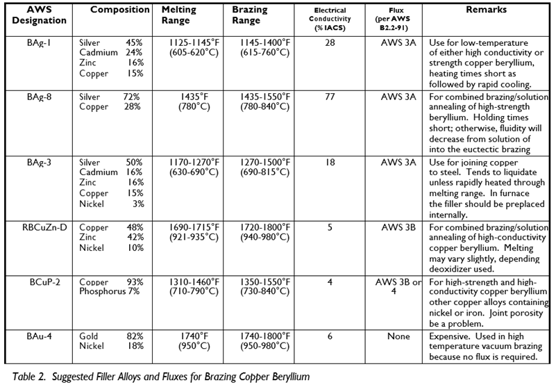
Aside from the requirements imposed by the configuration of the part and the copper beryllium alloy used, selection of the filler metal may also depend on such factors as corrosion resistance, strength, appearance, conductivity, flow characteristics and cost. Gold and copper base brazing alloys, because of their high melting temperatures are not generally used. Suggested brazing alloys for copper beryllium are described in Table 2. Some of the alloys in the table melt over a range, and it is the width of the range that determines the alloy's flow characteristics. A narrow melting range means the filler will flow more easily and be better suited for close tolerance brazing. Alloys with volatile constituents, such as zinc or cadmium, cannot be used when vacuum brazing.
Brazing alloy cost is largely dependent upon silver content. Copper phosphorous brazing alloys offer important advantages, though they lack the strength of conventional high silver alloys. When copper beryllium is brazed to steel, diffusion of beryllium into the brazing alloy can cause dewetting at the steel interface. A nickel containing filler such as BAg 3 should be used to avoid this problem.
The recommended flux for brazing high strength copper beryllium to itself or other common copper alloys, except aluminum bronze, is an alkali fluoride borate flux designated AWS 3A. It begins to melt and dissolve oxides at 600°F (315°C), is fully molten at 1100°F (590°C), and can be used at temperatures of 1145-1600°F (620 870°C). When brazing copper beryllium to aluminum bronze, use the chloride flux, AWS 4A. High temperature brazing operations, those using nickel silver fillers, require boron modified AWS 5A flux, which is effective above 1600°F (870°C).
There are two general methods for brazing copper beryllium, which differ mainly by the temperatures at which they are performed. The low temperature process (below 1140°F using AWS BAg 1, for example) is recommended for joining relatively small parts of approximately equal size. Rapid heating and cooling cycles with less than one minute dwell at the brazing temperature are the keys to obtaining a good bond. Heat is applied only to the joint area and followed by forced air or water quench. Hardness readings, without re aging, can be held to within a few Rockwell B points of the starting hardness if care is taken to avoid overheating or prolonged heating.
High temperature brazing methods are used for large parts or parts of dissimilar size. All customary heating methods are applicable. The choice of heat source will be governed by the required heating rate, part configuration, production quantities and rates, and cost considerations. Torch and induction heating are often selected for rapid heating rates. Of course, care must be taken with alloys of different thermal conductivity’s to ensure that all joint surfaces are uniformly heated. Rapid cooling of the parts from the brazing temperature will allow age hardening to the maximum mechanical properties of the alloy.
For high temperature brazing of high strength copper beryllium, the filler metal should melt at about 1400°F (760°C), a requirement met by AWS BAg 8. Assemblies should be heated to 1450°F (790°C) to allow the filler to flow. The assembly should be cooled to 1350 1375°F (730 745°C) before water quenching, followed by the usual age hardening at 600°F (315°C).
High temperature brazing of high conductivity copper beryllium alloys requires filler metals that flow between 1660 and 1740°F (900 950°C), e.g. AWS RBCuZn D (C77300) which melts at 1680°F (915°C). Lower melting alloys are not recommended unless considerable strength loss of the copper beryllium can be tolerated. Brazing high conductivity copper beryllium in the AT or HT condition, with filler metal melting at 1145°F (620°C), causes a loss of 10 15 Rockwell B points; more if the brazing time is extended.
Furnace brazing is more effective if the furnace is brought to temperature before the work is charged. Reducing atmospheres, such as dissociated ammonia, can decrease oxidation; however, a flux is still required to insure thorough wetting by the filler metal.
Resistance brazing takes advantage of copper beryllium’s high electrical conductivity, allowing the heat to be generated in the low conductivity filler metal in the joint. This technique is used extensively in brazing precious metal contacts to copper beryllium springs. Simple configurations produce uniform current densities, hence, the uniform temperatures required for good bonding.
In induction brazing, care must be taken to ensure that the coil design induces uniform temperatures at all joint surfaces. Note, higher conductivity alloys will heat at a slower rate. Brazing and cleaning operations should be performed in a well ventilated area to prevent worker exposure to airborne particulate material.
Braze joint design is no different for copper beryllium than for other alloys. Common sense, embodied in a few general rules, prevails. Proper joint clearances are always a compromise between the need to permit flux escape and the need to provide sufficient capillary to draw in filler metal. Clearances must be uniform and preferably in the range of 0.0015 0.003 inch (0.04 0.08 mm). The preplaced flux is displaced by the filler metal. When possible, the filler flow should be assisted by slight sliding or vibration of the work pieces. Dimensional changes with temperature should be calculated to assure proper clearance at the brazing temperature.
Thanks for joining me for another edition of In Our Element. For ongoing industry updates, connect with me on LinkedIn.
Processing beryllium-containing alloys poses a health risk if safe practices are not followed. Inhalation of airborne beryllium can cause serious lung diseases in some individuals. Occupational safety and health regulatory agencies worldwide have set mandatory limits on occupational respiratory exposures. Read and follow the guidance in the Safety Data Sheet (SDS) before working with this material. The SDS and additional important beryllium health and safety information and guidance can be found at berylliumsafety.com, berylliumsafety.eu and Materion.com. For questions on safe practices for beryllium-containing alloys, contact the Materion Product Stewardship Group at +1.800.862.4118 or contact us by e mail at Materion-PS@Materion.com.