Speed is an important consideration in engineering design. The kinetic energy of an object in motion is one half the mass times the square of the velocity. Kinetic energy is therefore a linear function of an object’s mass. Since mass is directly proportional to volume, and volume is a cubic function of length, kinetic energy increases as the cube of an object’s size, if scaled isometrically. Kinetic energy is also a function of the square of an object’s velocity. That energy doesn’t scale linearly with speed. If an object is traveling at twice its normal speed in a crash, it will have four times as much kinetic energy to dissipate, not twice as much. Doubling the speed quadruples the severity of a high-speed impact.
Increased speed also has two effects on the fatigue life (number of cycles to failure) of a part. For cyclically loaded components, a faster speed means that each cycle is completed more quickly, which gives it a higher strain rate. The fatigue life of most metals increases with strain rate due to strain rate hardening. However, this beneficial effect is offset by the fact that it will take less time to reach the point of failure, even if the total number of cycles is higher.
Example: In 1998, Inter-City Express train 884 derailed and crashed near Eschede, Germany, due to a wheel design which turned out to be inappropriate for use on high-speed trains. The previous wheels were monolithic (made entirely of one material – steel in this case), but the new wheel design featured a rubber dampener between the steel center hub and outer rim. This design is called a “resilient” wheel. The rubber is meant to dampen noise, shocks, and vibration. Resilient wheels had been, and still are, used safely and successfully on lower speed, light street cars and rail systems. However, they had not been used on a high-speed intercity train.
On that day, a fatigue crack went undetected on the inside of the rim of a wheel on the first car. The crack progressed outward until the rim fractured and peeled away. The broken steel rim embedded itself on the bottom of the car and caused the wheel to derail. That derailed wheel struck and activated a turnout switch, which caused the third and subsequent trailing cars to switch to an adjacent track where they also derailed. Those cars struck and destroyed the supports of a bridge, which fell and crushed some of the train cars. The trailing cars piled up against the bridge at 200 km/hr. Tragically, 101 people were killed and an additional 88 injured.
The originating crack went undetected because in the previous, all-steel wheel, fatigue cracks are usually more visible to inspectors. In that monolithic design, cracks are most likely to appear on the outside diameter, where the highest tensile stress occurs. In the resilient wheel, fatigue cracks could originate on the inside of the steel rim so they would likely not be seen under inspection until they progress to the point of catastrophic failure.
Figure 1 below shows a rough model of the peak tensile stress distributions of the wheels discussed.
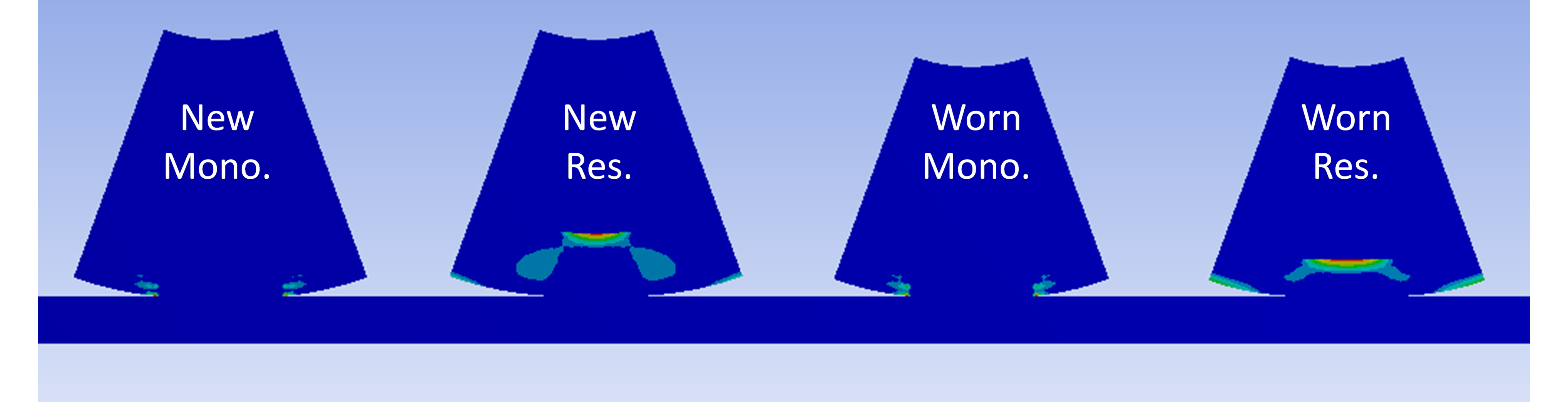
Figure 1. Tensile stress distributions on the different wheel types, before and after wear (as shown on simplified, two-dimensional “slices” of each wheel). The monolithic wheels show peak tensile stress on the outer rim. The resilient wheels show much higher peak tensile stresses on the inside diameter of the outer rims. The stresses are higher in the worn wheels than in the new wheel. Numbers are not shown because this is a qualitative, not quantitative analysis due to the many simplifications and approximations.
There were four factors in the use of the resilient wheel on the high-speed train that contributed to its failure in this application:
Engineers can take an important lesson from this example in that even if a design is proven to work at low speed, it may not work at high speed without extensive modifications. Higher speeds can greatly accelerate the failure process, and at a rate disproportionate to the increase in speed.
Thanks for joining me for another edition of In Our Element. For ongoing industry updates, connect with us on LinkedIn.