The range of wavelengths over which optical coatings perform their various functions is large. Figure 1 shows the spectrum extending from short wavelengths (UV) to long wavelengths (IR). UV and Visible light of high photon energies is radiated from solar and artificial light sources. The Short Wave IR (SWIR) and Mid-wave IR (MWIR) regions overlap reflected solar and thermally emitted energies. At LWIR wavelengths, energy is emitted from the source due to its temperature. Optical components and instruments that operate at long wavelengths in the infrared spectrum require a different set of coating materials than those that operate in visible wavelengths. Materion offers a comprehensive range of coating materials, plus our technical experts can determine the optimal coating materials to meet your wavelength requirements. IR materials differ in chemical composition and spectral transmission and are also less mechanically durable than materials used in the Visible and shorter wavelengths. This article will focus on IR coating applications, coating materials, their properties, and deposition behavior.
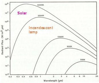
Figure 1. Spectral emission from black body radient sources of various temperatures. Emission from IR sources (low temperature emitters) is 5 orders of magnitude lower compared with tungsten lamps that emit visible energy. (from Ref 1).
Figure 2. shows the spectral regions from visible to long-wave IR and their associated wavelengths. Detection and imaging of specific spectral bands of energy within these general regions are optimized according to requirements and applications. Some examples follow. Energy at wavelengths in the SWIR band is reflected by a remote scene and sensed by orbiting instruments. Or, this energy is reflected by human skin, and used in medical disease sensing and diagnosis. Information is detected as differences between reflected and absorbed wavelengths in these applications. For example, blood oxygenation in the circulatory system can be monitored at specific absorbed wavelengths. Similarly, chlorophyl absorption density is an indicator of vegetation health. In addition to solar natural light, artificial light sources are used outside the visual range of wavelengths. Reference 2 contains visual display images taken with different wavelengths, and illustrates how differences can be detected at wavelengths outside our visually percieved wavelength sensitivity. Referring to Figure 1, at long wavelengths, the energy emitted by a warm body might exceed the energy reflected by that body’s surface. This phenomenon governs the operation of thermal IR sensing in the LWIR.
Laser sources operating in the SWIR band are used for medical (ophthalmic) and military devices. In some cases, the coating for optical surfaces needs to have high resistance to laser-induced damage, and this requirement imposes a challenge to coating materials and deposition technology. The MWIR band of wavelengths overlaps scene information contained in reflected solar irradiance and information thermally emitted by the scene, and is therefore useful in remote-monitoring of earth, ocean and climate changes as well as tissue health in the medical field. LWIR instruments sense thermal emission instead of reflection, and have application in imaging warm sources behind smoke and dust in military imaging devices and as an aid to firefighting. It is also useful in identifying abnormal localized heating that might result form the presence of circulatory problems or tumors in humans.
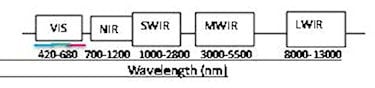
Figure 2. Spectrum wavelengths and region labels
IR sensors covering the entire IR spectrum monitor earth and atmospheric resources from space- and aircraft-based platforms. There are also imagers for detection and tracking in the military arena, and laser-based instruments for medical and defense, as well as for research and other scientific applications. To survive and operate in punishing environments such as high-velocity rain drop and sand impact, or wide temperature swings, optical coatings on optical domes and windows require extraordinary wear resistance. Hypervelocity military aircraft and missiles, and high-mileage commercial aircraft are typical applications for durable coatings that operate in the thermal IR region - wavelengths 8 to 12 µm. Coating materials and deposition processes have been specially developed to meet these challenges.
Table 1 lists the common substrates used to manufacture IR lenses, windows, and domes. They are diverse in chemical composition, a fact that requires special consideration when it is necessary to deposit functional and durable thin film coatings on their surfaces. Often an intermediate layer material is required to initiate nucleation and strong bonding between substrate and first-coated layer.
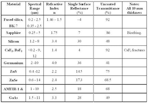
Table 1. IR substrate materials and their properties. Transmission limits are for internal transmittance >90%.
The IR coating materials used must possess high transmission in the wavelength regions that are transmitted by the substrate. A distinct division in usable material composition occurs near wavelengths between the Mid-Wave IR (MWIR) and LWIR. Oxide compounds are transparent at wavelengths shorter than ~7000 nm (7 µm). There, oxide compound materials provide the low-, medium-, and high- refractive indices required in the design of coatings and their deposition. At wavelengths longer than ~7 µm, the corresponding available material choices are Fluoride and element group IIB-VIA (ZnS and ZnSe) compounds and Ge. Table 2 lists general spectral transparency limits and deposition properties for the common coating materials. Some Oxide compounds and their mixtures (discussed in previous CMN issues) exhibit reasonably high transparency to 10+ µm when restricted to layer thickness.
Extremely hard wear-resistant coatings, such as diamond-like carbon (DLC), BP and other boron-based compounds, are produced by reactive processes such as CVD. They are not starting materials.
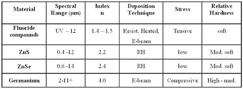
Table 2. General deposition properties of IR coating materials.
For several decades, Thorium fluoride was used exclusively as the low-index material in combination with ZnS to make LWIR coatings. Because ThF4 is a radioactive alpha emitter, it was prohibited from use in coating military optics, and many groups worldwide investigated alternate non-radioactive compounds to find a suitible substitute [3]. Today, a handful of substitute materials are in use, some with transmission and mechanical properties equivalent to ThF4. Table 3 lists the optical properties of commonly used coating materials for MWIR to LWIR wavelengths. MWIR coatings can be made using Oxide compounds, from which durable multi-layer coatings can be produced.
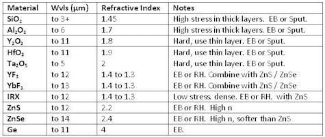
Table 3. Coating materials useable to the stated IR wavelength limit. No materials are radioactive.
Suggested deposition parameters for Fluoride compounds are: e-gun power 6 kV, typically lower than that used for oxide evaporation, and beam current ~50 mA. Chamber base pressure: P ~5 e-06 Torr. Sweep the beam over the material load to melt thoroughly. Low power should be applied for up to the four minutes to drive off adsorbed water, prevent spitting, and form a uniformly melted evaporation surface. Evaporation rate: 10 to15 Å/s. Maintain substrate temperature ~160° C. The evaporation source can alternatively be an uncovered resistance-heated moly boat. Slow power ramp-up to melt the charge is necessary as above. For all Fluoride compounds, higher substrate temperatures approaching 200° C result in higher packing density and consequently higher indices and lower water band depths. However, when paired with ZnS, temperatures higher than ~175° C reduce the condensation (growth) rate of ZnS layers, thus complicating accurate thickness monitoring.
Technical data sheets that are guides for deposition are available online [4] in the Resource Center. The user must bear in mind that such variables as pumping capacity, and therefore pressure and water vapor concentration control, will affect the process for Fluoride film growth.
Fluoride compounds from the list of candidates with known LWIR transparency are constantly being refined as starting materials in an attempt to improve their evaporation behavior. Fluorides have potentially problematic properties that impose difficulties during the production of multi-layer coatings: water affinity, low packing density and tensile stress. Modifications of preparation procedures are underway to reduce the effects mentioned. A material with recently improved behavior is YF3. A transmittance curve showing high transparency to ~12 µm for a 15kÅ thickness deposited on Cleartran is shown in Figure 3.
![]()
Figure 3. Transmittance of YbF3 with thickness15kÅ deposited at 150° C. Absorption bands due to included water appear at 2.9 and 6.1 µm in all pure Fluoride compound materials. They are reduced in depth at higher substrate temperatures.
Fluoride compounds grow with a columnar microstructure that contains a large void volume that water vapor can occupy when the thin film layer is exposed to the atmosphere. The dimensions of the structure are largest under low-energy deposition processing such as E-beam or resistance-heated evaporation. The addition of impacting energy by using IAD or sputtering, reduces the columnar growth dimension. Columnar / micro-crystalline microstructure also exhibits high tensile stress, and thick Fluoride coatings often relieve stress to form tensile crack patterns. Simultaneously, water vapor can permeate the film void volume and change optical properties and adhesion strength. ZnS exhibits compressive stress that partially compensates for the total tensile stress of the complete coating design. However, in a typical filter, the thickness of the Fluoride layers is 2/3 of the total design thickness, so the residual stress is tensile in nature. Advances in material preparation, demonstrated by mixed materials such as IRX, have produced a Fluoride material whose nanostructure is amorphous and dense, and therefore its transmission spectrum exhibits shallower water bands. It also exhibits greater mechanical durability and lower tensile stress. IRX is more stable under environmental stresses that pure Fluorides. A small % additive inhibits the formation of large crystallite columnar growth micro-structure, and promotes a more compact (dense) structure.
Coating designs for components such as filters benefit when the index contrast is large. Some complex designs require a total thickness as large as 4-5 µm, and are thus prone to high accumulated mechanical stress that threatens the physical integrity of the coating. Fewer layers are required when the indices have a large difference in value, and this thinner combination results in lower stress. For the combination ZnS / Fluoride, the index ratio at 10 µm wavelength is ~1.6. For the combination Ge / Fluoride, the ratio is ~3, suggesting that this combination has advantages. However, Fluoride layers are not compatible with Ge surfaces. A thin layer of a binding material must be inserted between these layers which complicates the design. ZnS and Ge surfaces are compatible, and produce a desirable index ratio of ~1.8. Many IR designs are based on this latter combination of materials, with outer layers requiring a Fluoride to maximize performance (minimize reflectance).
This is a brief introduction to IR coating materials and their deposition technology. Ongoing research ensures that advancements will continue to be made in this field.
1. James D. Rancourt, Optical Thin Films User’s Handbook, 1994, McGraw Hill.
2. Austin A. Richards, Alien Vision: Exploring the Electromagnetic Spectrum with Imaging Technology, Second Edition (SPIE Press Book).
3. Pellicori, S. F. and E. Colton, "Fluoride Compounds for IR Coatings”, Thin Solid Films 209,109 (1992).
For more information, contact the authors:
David Sanchez, Editor
Sr. Materials & Applications Scientist
Materion Electronic Materials
Email: david.sanchez@materion.com
Samuel Pellicori, Principal Contributor
Pellicori Optical Consulting
PO Box 60723, Santa Barbara, CA 93160
Email: pellopt@cox.net