Author: Sam Pellicori
Editor: David Sanchez
In this issue of Coating Materials News & More (CMN), we review essential considerations related to producing stable optical coatings and materials for use in spaceflight applications. We provide an overview of the challenges optical materials face when exposed to high-energy radiation and atomic oxygen in Earth's orbit. Additionally, we discuss strategies for mitigating damage to these optics.
In addition to high vacuum and differing thermal exposure, the space environment contains zones of high energy radiation and highly reactive atomic oxygen (AtOx). The materials in optical instruments are required to provide stable performance during their residence in orbit environments. Previous CMN newsletters have discussed different aspects of this topic [1, 2].
Early space instrumentation gathered data on the effects of 5.7 years (1984-1990) of space exposure on the Long Duration Experiment Facility (LDEF). Orbital altitude was 400 km, decaying to 286 km when it was retrieved. The optical coatings of the filters and mirrors aboard the spacecraft consisted of “soft” materials deposited by low energy (thermal) processes. These optical specimens were exposed to the dense concentration of AtOx at altitudes ranging from 180km to 650 km. Optical testing of the retrieved specimens contributed to the development of materials and deposition processes that provide higher stability when exposed to the space environment. Optical coatings and other materials in Low Earth Orbit (LEO) have more recently been exposed on the Materials International Space Station Experiment (MISSE-7). Samples included improved coating materials and high-energy deposition processes such as magnetron sputtering. [2, 3].
Communications satellites, constellations of internet-of-space microsatellites for broadband internet access, and remote sensing satellites reside in LEO at altitudes from 160 km to 2,000 km. Medium Earth Orbit (MEO) at altitudes from approximately 2000 km to approximately 36000 km is commonly used for navigation systems. In the environment outside the earth’s atmosphere, damage to the properties of optical materials can result from exposure to the ionizing, particulate, UV and reactive chemical interactions. Since most spacecraft occupy LEO and MEO orbits, we concentrate on exposure effects in these environments. At higher orbits and entering into deep space, the contributions of solar and atmospheric influences diminish with distance, and high-energy cosmic radiation becomes dominant. The radiation environment in more distant orbits: Global Positioning Satellites (GPS, 22000 km), Geostationary (GEO, 35700 km) and High Earth Orbit (various ~100,000 km) include solar emission, high fluences of trapped electrons, and fewer protons.
Damage from micrometeorite impact is another threat to optical surfaces, especially to solar panel arrays. The density of impacts depends on their direction and incidence angle at the surface. Thin glass covers cemented to the cell surface using radiation tolerant silicone cements protect against micrometeorite impact damage. The outer surfaces of the cover glass are coated with UV-reflecting wide-band AR coatings deposited by magnetron sputtering using radiation-resistant oxide compounds [3].
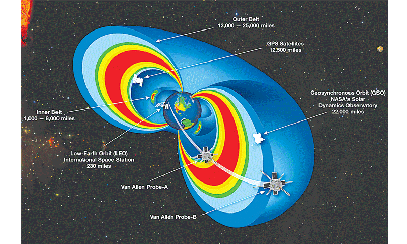
Figure 1. Trapped radiation belt orbits. The International Space Station, climate monitoring and space internet satellites reside in Low Earth Orbit (LEO).
GPS and scientific instruments are stationed in GEO Synchronous Orbits. (Source: NASA.com)
The potentially damaging environment encountered by spacecraft in LEO and GEO orbits consists of solar UV photons, atomic oxygen (in LEO), solar flare protons, heavy ions, and protons and electrons trapped in belts by the Earth’s magnetic field. Table 1 lists the concentrations in each orbit [4,5].
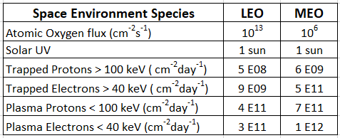
Table 1. Orbital concentrations of the various space environment hazards.
Table 2 lists the modeled doses of protons and electrons accumulated in LEO and GEO orbits [6]. Spacecraft housing provides significant reduction of the higher energies of particles, leaving lower energies that can be stopped in internally located optical materials where they inflict radiation-induced damage.
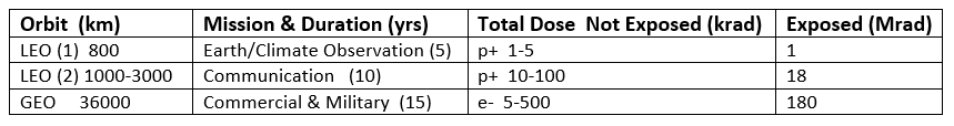
Table 2. Doses of protons and electrons accumulated during mission lifetimes in LEO and GEO,
modeled for exposed and internal materials (adapted from [6]).
Commercial and military reconnaissance satellites orbit in the trapped ionizing radiation belts and have projected operational lifetimes of 15 years. The exposed surfaces of their solar cell panels require resistance to radiation-induced power loss to ensure long operational lifetimes.
Atomic oxygen is generated by the dissociation of oxygen (O2) by solar UV at wavelengths <250 nm. The highest concentration of atomic oxygen resides at 180 to 650 km altitudes and reactive energy is ~ 5 eV. AtOx can oxidize silicones and metal surfaces and break down polymers to form volatile contaminants. Erosion can penetrate to millimeters (mm) in depths in some materials leaving rough surfaces that can entrap contaminates. Abrasion-like erosion of surfaces that results from head-on impact (in the ram direction) creates scattering surfaces. High and low-energy protons in Low Earth Orbit can induce absorption, increasing transmission losses in optical coatings and materials [7]. The high electron density in Geosynchronous Earth Orbit primarily affects electronics and has little effect on optical coatings. Solar UV presents an existing threat to coating and materials stability in both Low Earth Orbit and Geosynchronous Earth Orbit. The thousands of square meters of solar panels that power nearly all space instruments have UV reflecting and stable AR coatings to ensure adequate end-of-life performance. The International Space Station and communications satellites orbit in LEO orbits where the energy and flux of protons and atomic oxygen concentrations are high.
Space instruments are designed to survive a specified total absorbed radiation dose budget expressed in Rads (radiation absorbed dose) for the lifetime of the mission. Typical optical instrument design specifications are for total mission doses ~ 30 kRad. An aluminum shield ~1 mm thick stops electrons and protects electronics. High energy ions and protons can cause showering of lower energy particles from housings. Highly sensitive devices exposed to the high energy radiation of deep space require a shield of tungsten. Optical surfaces that are exposed must be inherently resistant and stable to radiation, UV, and AtOx exposure. Achieving resistance requires attention to coating materials and their deposition processes. Generally, selecting metal oxide compounds and deposition with high purity and high packing density processes are necessary to produce coatings that are stable in the space environment.
Radiation induced damage (RID) mechanisms involve ionization, and atomic displacement and defect generation, any of which create absorption. Ionizing radiation includes protons and ions whether trapped or transient from solar flare activity. In the Figure 2 illustration below, the high- and low-energy particulates are separated by their approximate penetration energies. As the energetic particle is stopped, its energy is dissipated in the film, causing damage. UV photons typically penetrate thin film coatings without causing damage unless absorption is present. Coating materials are chosen that are transparent to as short a UV wavelength as practical for their intended application. Materials used in UV wavelengths include transparent metal oxide compounds which are the high-index component of multi-layer coatings, tantalum oxide (Ta2O5), hafnium oxide (HfO2), zirconium oxide (ZrO2), yttrium oxide (Y2O3), and aluminum oxide (Al2O3). These compounds are paired with silicon dioxide (SiO2). The short wavelength limit for oxide compounds at which their extinction coefficients, k, are <~0.001 is ~220 nm.
Low energy protons can cause atomic displacement and ionizing damage, such as color center creation, if the energy is dissipated within the depth of the coating or material. Bandpass filters can consist of multi-layers with total thickness exceeding 10 µm. Figure 2 illustrates the damage sites of LEO protons of energy <~ 50 keV can occur in coatings of this or smaller thickness because the penetration depth for the metal oxide layer composition is < ~10 µm. Higher energies penetrate the coating without damage. The penetration depth for 100 keV monoenergetic protons in a 2 µm-thick high reflector for 1064 nm is calculated to be ~1.7 µm. Therefore, radiation damage is expected for this high reflector ( HR) in space [2]. Higher energies pass through without depositing energy, and no damage occurs in the optical coating. Damage centers for high energy radiation can be generated in the substrate if the substrate material is not resistant to that radiation, and darkening can occur with accumulated dose [8, 9].

Figure 2. The primary damage sources in the space environment and their sites of influence in optical materials.
High energies penetrate coatings and might cause radiation induced damage effects in substrates.
The extraterrestrial solar UV spectrum unfiltered by the stratospheric ozone layer includes energy at wavelengths as short as ~200 nm. While solar radiance falls to very small values at those short wavelengths, the corresponding energies of UV photons are as high as 6 eV. Energy of 4 eV (~300 nm) can induce absorption in coatings and cemented cover glasses used in space power solar cells. Materials and deposition processes have been developed and proven to be stable, suffering minimal transmission loss to UV, protons and AtOx reaction [3, 9, 10].
Atomic oxygen is an energetic plasma source with high chemical reactivity. The damage mechanism with AtOx is chemical disruption/reaction and chemical-mechanical erosion. Polymers and composites are especially vulnerable to oxidation reactions with AtOx and are sources of contamination that can deposit on optical surfaces [7]. Under UV or ionizing radiation, the contaminates degrade optical performance by introducing transmission loss and increased light scatter. These effects are especially severe at short wavelengths and have the largest impact on UV instruments.
The stability of optical glasses has been studied, and results presented [6, 9]. In addition to transmission loss with high energy radiation, refractive index and dimensional changes have been observed. The long glass paths in fiber optics are especially vulnerable to transmission loss from ionizing radiation exposure. Two measures are in place to reduce signal loss. Glass is doped with, for example, Ce3+ ions to reduce darkening that occurs at short wavelengths. Where appropriate, longer wavelengths in the NIR and SWIR where radiation-induced losses are low are used.
Optical coatings on exposed windows and mirrors, and internal optical surfaces are vulnerable to radiation-induced absorption increases despite their thin dimensions. Low energy particles, UV and AtOx can damage coatings. To reduce susceptibility to these space elements, coating materials and deposition processes that provide extended mission lifetimes in the orbital environments have been developed [3, 8, 9, 10]. Coatings that provide resistance and stability in exposure to high energy and reactive space environments consist of hard oxide materials that are deposited with high-energy processes. These processes include magnetron or ion-beam (IBS) sputtering, plasma ion-assisted deposition (PIAD), and IAD E-beam [3, 10]. They also supply high ion energies that increase packing density by preventing porous crystallite columnar growth. Displacement, defect and impurity concentrations are minimized, and the resultant coating has the mechanical and optical properties of the bulk material.
Stable coating materials for the space environment include SiO2 (the low-index component) combined with Ta2O5, HfO2, ZrO2 and others. [3, 8, 10]. These oxide compounds have high bandgap energies therefore they are transparent to UV or near-UV wavelengths. Fluoride compounds also have large bandgaps; however, they lack the chemical (compositional) stability that oxide compounds have in the terrestrial environment, extraterrestrial radiation and AtOx exposure. Surface protection against AtOx can be achieved by the application of a ~100 nm of metal film or metal oxide layer. Examples of protective coating materials include SiO2, Al2O3, ITO, Al, and Au [7].
To prevent vacuum welding of contacting surfaces, metals are coated with layers of Moly disulfide (MoS2) or diamond-like coatings (DLC). These non-optical coatings provide lubricity without outgassing contaminating volatiles.
Together with high energy deposition processes for environmental stability is the state and preparation of the starting material, especially for E-beam processes. Materials are refined to reduce multiple oxidation states and impurities that might stimulate absorption. Density is maximized to exclude trapped volatiles, and the starting form is optimized for evaporative or sputtered deposition processes. Densification of growth structure with high deposition energy was discussed in a past CMN issue using the structural zone model (SZM) [11]. Past CMNs have also explained how the addition of a small amount of a mutually soluble material promotes dense growth structure. This happens even at lower than typical substrate temperatures by discouraging columnar (porous) growth. This technique also applies to mixed oxide and mixed fluoride compounds.
Optical coatings and materials used in the space environment face challenges that do not exist in earth-bound applications. A large amount of experimental and operational experience has accumulated over the decades to provide space instrument designers and fabricators with stable materials and processing choices. Spacecraft lifetimes have consequently been expanded, thus reducing replacement costs, and increasing reliability.
1. Samuel Pellicori, “Coatings Used in Space”, Coating Materials News Vol 26 Issue 2.
2. Samuel Pellicori, “Optical Coatings for Harsh Environments”, Coating Materials News Vol 26 Issue 3.
3. Samuel F. Pellicori, Carol L. Martinez, Paul Hausgen, and David Wilt, “Development and testing of coatings for orbital space radiation environments”, Applied Optics, 53(4) 339-350 (2014).
4. C.J. Panetta, P.D. Fuqua, J.D. Barrie, C.T. Chu, and D.R. Alaan, “Lessons Learned from Optics Flown on the Materials International Space Station Experiment”, OIC conference, Whistler, Canada, June 2013.
5. C. J. Panetta, P. D. Fuqua, J. D. Barrie, D. R. Alaan, C.-T. Chu and M. J. Meshishnek, "Characteriza0on of Optical Samples Flown on MISSE‐7" ATR--‐2011(8402)--‐5. The Aerospace Corporation (2012), internal report.
6. Michel Fruit, Andrei Gusarov, Francis Berghmans, Dominic Doyle, “Radiation Impact on the Characteristics of Optical Glasses Test results on a Selected Set of Materials”, Proc. of SPIE Vol. 10569 105691R-1 (2000).
7. Bruce A. Banks, Sharon K. Miller, and Kim K. de Groh, “Low Earth Orbital Atomic Oxygen Interactions with Materials”, NASA/TM—2004-213223.
8. Denny Wernham and Angela Piegari, “Optical coatings in the space environment”, Chapter 22. Optical Thin Films and Coatings, eBook ISBN: 9780081020999.
9. Tammy Henson and Geoffrey Torrington, “Space radiation testing of radiation-resistant glasses and crystals”, Proc. SPIE. 4452, Inorganic Optical Materials III (2001).
10. Samuel F. Pellicori and Carol L. Martinez, “UV Optical Properties of Thin Film Oxide Layers Deposited by Different Processes”, Vol. 50, No. 28 5559, Appl. Opt. 1 October 2011.
11. Samuel Pellicori, "Fundamentals of Thin-Film Growth & Influences on Mechanical and Environmental Durability Properties", Coating Materials News Vol 28 Issue 2.