We introduced tensile testing and discussed how it can help find critical material properties like yield strength. The yield strength (also known as the proof strength) may be the most important material property to consider when designing components like electronic and electrical contacts and connectors. However, in most cases yield strength is a derived property, and not a well-defined point on the stress-strain curve where material behavior changes. The test results must be evaluated, and more than one test should be performed to confirm the yield strength. In fact, there are several types of yield strengths, each with its own definition. To know how strain will impact your components, it’s a good idea to know the different types in order to understand which most effects your application.
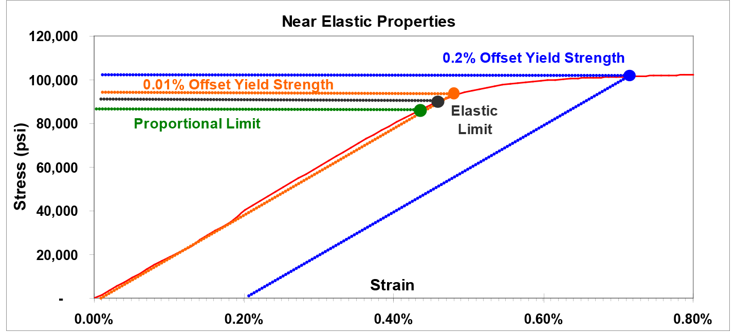
The stress and strain displayed in the first portion of a material’s stress-strain curve are linearly proportional to each other. This relationship forms a straight line on the stress-strain diagram, with a slope known as the elastic modulus of the material. The stress level at which the stress-strain response first begins to deviate from linear behavior is known as the proportional limit, shown below as the green line in Figure 1. The proportional limit is the maximum stress at which the material will continue to show elastic deformation.

Figure 1. Stress-Strain Curve in Near-Elastic Region
The name “yield strength” seems to imply that it is the level of stress at which a material under load ceases to behave elastically and begins to yield. This is not the case. The point at which the material first begins to experience permanent set is known as the elastic limit (shown as the black line in Figure 1 above). Material that is loaded to a stress level below the elastic limit will completely return to its original size and shape if the load is released immediately. Conversely, material that is loaded to a stress level greater than the elastic limit will experience some degree of permanent set. The yield strength is defined as the level of stress that produces a specific amount of permanent set. This means that by the time the yield strength is reached, the base material has already yielded (undergone permanent set), by definition.
The 0.2% offset yield strength (0.2% OYS, 0.2% proof stress, RP0.2, RP0,2) is defined as the amount of stress that will result in a plastic strain (permanent deformation) of 0.2%, illustrated by the blue line in Figure 1 above. This is the yield strength that is most often quoted by material suppliers and used by design engineers. If a different permanent set is specified, then there will be a different yield strength associated with that strain level. For example, the orange line in Figure 1 would represent the 0.01% offset yield strength. In some cases, particularly with low strength rod or wire, it is difficult to accurately measure the plastic strain. In this case, the total strain is measured and the 0.5% extension under load yield strength (0.5% EUL, RT0.5) is listed instead.
Another popular property often specified by material suppliers and designers is the spring bend limit. This is not found in the uniaxial tension test and must be determined by its own specific spring bend limit test. In this test, a small sample of strip is repeatedly loaded and unloaded and bent in small increments until permanent set is observed. This is similar to how the precision elastic limit is determined in tension testing. There are several spring bend limit tests in use today. Interestingly, there appears to be no general correlation between the results from different spring bend limit tests, nor between the results from any spring bend limit test and the precision elastic limit test. Additionally, the spring bend limit is sensitive to the orientation of the sample (i.e., coilset-up or coilset-down orientations).
To ensure that a designed connector does not yield when in use, the calculations for the desired stress of the design should include a safety factor to allow an additional margin of error to account for unforeseen circumstances. A maximum stress level of 75% of the yield strength (corresponding to a safety factor of 1.0 / 0.75 = 1.33) has historically been used. Recently, the predictive capability of finite element analysis has allowed designs to proceed with safety factors approaching or even descending below 1.0 if a minor amount of permanent set is not detrimental and can be tolerated.
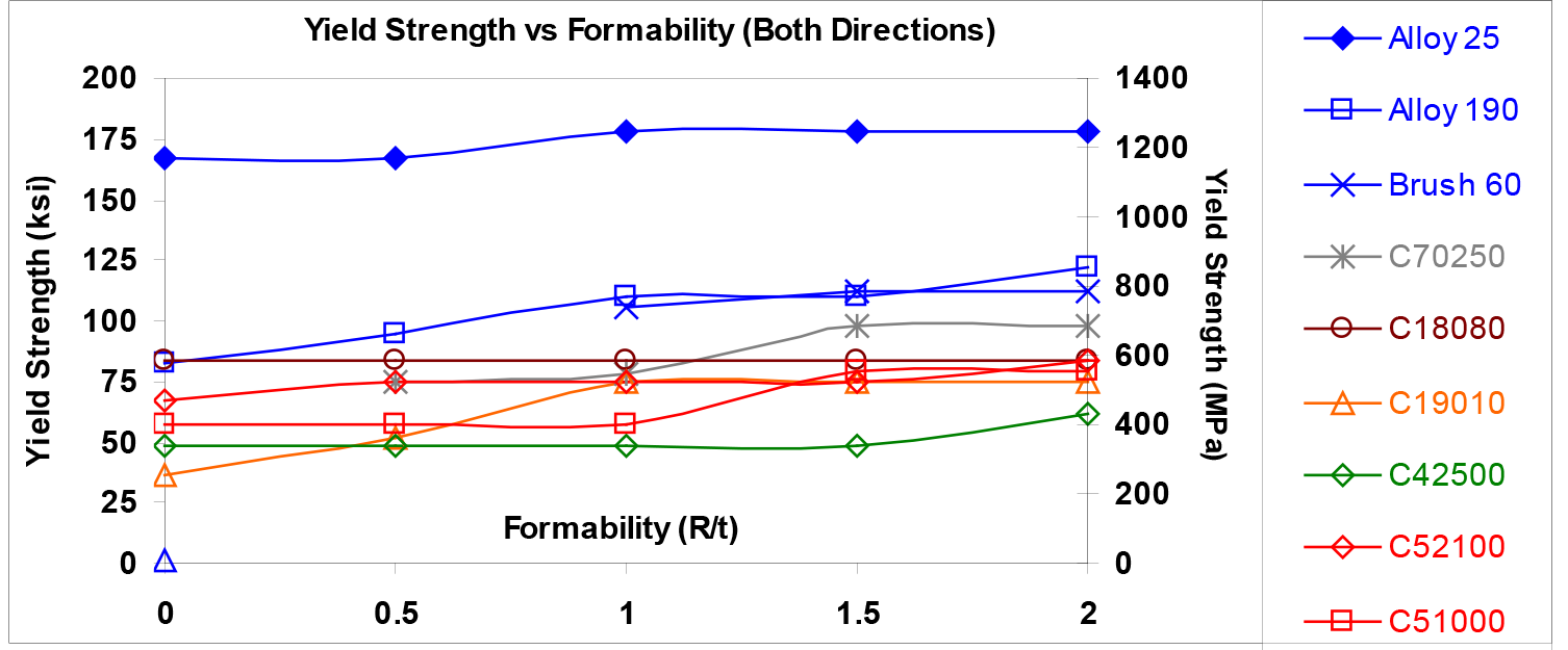
When designing a contact, materials with greater yield strengths will usually provide greater design flexibility by allowing for higher stress levels. However, since formability generally tends to decrease as yield strength increases, higher strength tempers of a given material will offer less design flexibility than the lower strength tempers. That means it is imperative to find the material with the highest strength that also meets the formability requirements of the design. Figure 2 below shows the 0.2% offset yield strength as a function of formability for copper alloys commonly used in connector applications. The copper-beryllium alloys shown in blue offer the greatest yield strength for a given formability level, and vice versa. These alloys will provide designers with the optimal amount of flexibility for a given strength level.

Figure 2. Yield Strength vs. Formability for Common Copper-Based Connector Alloys
There are many ways to define yield strength, but no matter which way you choose, knowing a material’s yield strength is a crucial part of understanding how a component will function. It’s vital to know a material’s yield strength, but it is only one piece of data. When testing potential materials, consider which factor is most important for your needs and make sure you test accordingly. The right material can make a huge difference in the performance of your design.
Learn more about material strain testing, see our related blogs: